- 您现在的位置:买卖IC网 > Sheet目录108 > SBL1645CT (Diodes Inc)DIODE SCHOTTKY 45V16A TO220-3
DS23014 Rev. 8 - 3
1 of 3
www.diodes.com
SBL1630CT - SBL1660CT
? Diodes Incorporated
NOT RECOMMENDED
FOR NEW DESIGN
SBL1630CT - SBL1660CT
16A SCHOTTKY BARRIER RECTIFIER
Features
?
Schottky Barrier Chip
?
Guard Ring Die Constructi
on for Transient Protection
?
Low Power Loss, High Efficiency
?
High Surge Capability
?
High Current Capability and Low Forward Voltage Drop
?
For Use in Low Voltage, High Frequency Inverters, Free
Wheeling, and Polarity Protection Applications
?
Lead Free Finish, RoHS Compliant (Note 3)
Mechanical Data
?
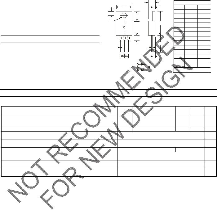
Case: TO-220AB
?
Case Material: Molded Plastic. UL Flammability
Classification Rating 94V-0
?
Moisture Sensitivity: Level 1 per J-STD-020C
?
Terminals: Finish –Tin. Solderable per MIL-STD-202,
Method 208
?
Polarity: As Marked on Body
?
Marking: Type Number
?
Weight: 2.24 grams (approximate)
L
M
A
N
P
D
E
K
C
B
G
12 3
J
HH
Pin 1 +
Pin 3 +
Pin 2 -
Case
+
TO-220AB
Dim Min Max
A
14.48 15.75
B
10.00 10.40
C
2.54 3.43
D
5.90 6.40
E
2.80 3.93
G
12.70 14.27
H
2.40 2.70
J
0.69 0.93
K
3.54 3.78
L
4.07 4.82
M
1.15 1.39
N
0.30 0.50
P
2.04 2.79
All Dimensions in mm
Maximum Ratings and Electrical Characteristics @T
A
= 25°C unless otherwise specified
Single phase, half wave, 60 Hz, resistive or inductive load.
For capacitive load, derate current by 20%.
Characteristic Symbol SBL
SBL
SBL
1630CT
1635CT
1640CT
1645CT
1650CT
SBL
SBL
SBL
1660CT
Unit
Peak Repetitive Reverse Voltage
Working Peak Reverse Voltage
DC Blocking Voltage
VRRM
VRWM
VR
30 35 40 45 50 60 V
RMS Reverse Voltage
VR(RMS)
21 24.5 28 31.5 35 42 V
Average Rectified Output Current
(Note 1) @ TC
= 95
°C
IO
16 A
Non-Repetitive Peak Forward Surge Current 8.3ms
Single Half Sine-Wave Superimposed on Rated Load
IFSM
250 A
Forward Voltage Drop
@ IF
= 8.0A, T
C
= 25
°C VFM
0.55 0.70 V
Peak Reverse Current
@TC
= 25
°C
at Rated DC Blocking Voltage @ TC
= 100
°C
IRM
0.5
50
mA
Typical Junction Capacitance (Note 2)
Cj
700 pF
Typical Thermal Resistance Junction to Case (Note 1)
RθJC
3.5
°C/W
Operating and Storage Temperature Range
Tj, TSTG
-65 to +150
°C
Notes: 1. Thermal resistance junction to case mounted on heatsink.
2. Measured at 1.0MHz and applied reverse voltage of 4.0V DC.
3. RoHS revision 13.2.2003. Glass and high temperature solder exemptions applied, see EU Directive Annex Notes 5 and 7.


发布紧急采购,3分钟左右您将得到回复。
相关PDF资料
SBL1660PT
DIODE SCHOTTKY 16A 60V TO3P-3
SBL2060PT
DIODE SCHOTTKY 20A 60V TO3P-3
SBL3030PT-E3/45
DIODE SCHOTTKY 30V 30A TO-247AD
SBL3040CT
DIODE SCHOTTKY 30A 40V TO220-3
SBL3060PT
DIODE SCHOTTKY 30A 60V TO3P-3
SBL30L30CT
DIODE SCHOTTKY 30A 30V TO220-3
SBL4040PT-E3/45
DIODE SCHOTTKY 40V 40A TO-247AD
SBL4060PT
DIODE SCHOTTKY 40A 60V TO3P-3
相关代理商/技术参数
SBL1645PT
功能描述:肖特基二极管与整流器 16A 45V RoHS:否 制造商:Skyworks Solutions, Inc. 产品:Schottky Diodes 峰值反向电压:2 V 正向连续电流:50 mA 最大浪涌电流: 配置:Crossover Quad 恢复时间: 正向电压下降:370 mV 最大反向漏泄电流: 最大功率耗散:75 mW 工作温度范围:- 65 C to + 150 C 安装风格:SMD/SMT 封装 / 箱体:SOT-143 封装:Reel
SBL1650
功能描述:肖特基二极管与整流器 16A 50V RoHS:否 制造商:Skyworks Solutions, Inc. 产品:Schottky Diodes 峰值反向电压:2 V 正向连续电流:50 mA 最大浪涌电流: 配置:Crossover Quad 恢复时间: 正向电压下降:370 mV 最大反向漏泄电流: 最大功率耗散:75 mW 工作温度范围:- 65 C to + 150 C 安装风格:SMD/SMT 封装 / 箱体:SOT-143 封装:Reel
SBL1650CT
功能描述:肖特基二极管与整流器 16A 50V RoHS:否 制造商:Skyworks Solutions, Inc. 产品:Schottky Diodes 峰值反向电压:2 V 正向连续电流:50 mA 最大浪涌电流: 配置:Crossover Quad 恢复时间: 正向电压下降:370 mV 最大反向漏泄电流: 最大功率耗散:75 mW 工作温度范围:- 65 C to + 150 C 安装风格:SMD/SMT 封装 / 箱体:SOT-143 封装:Reel
SBL1650PT
功能描述:肖特基二极管与整流器 16A 50V RoHS:否 制造商:Skyworks Solutions, Inc. 产品:Schottky Diodes 峰值反向电压:2 V 正向连续电流:50 mA 最大浪涌电流: 配置:Crossover Quad 恢复时间: 正向电压下降:370 mV 最大反向漏泄电流: 最大功率耗散:75 mW 工作温度范围:- 65 C to + 150 C 安装风格:SMD/SMT 封装 / 箱体:SOT-143 封装:Reel
SBL1660
功能描述:肖特基二极管与整流器 16A 60V RoHS:否 制造商:Skyworks Solutions, Inc. 产品:Schottky Diodes 峰值反向电压:2 V 正向连续电流:50 mA 最大浪涌电流: 配置:Crossover Quad 恢复时间: 正向电压下降:370 mV 最大反向漏泄电流: 最大功率耗散:75 mW 工作温度范围:- 65 C to + 150 C 安装风格:SMD/SMT 封装 / 箱体:SOT-143 封装:Reel
SBL1660CT
功能描述:肖特基二极管与整流器 16A 60V RoHS:否 制造商:Skyworks Solutions, Inc. 产品:Schottky Diodes 峰值反向电压:2 V 正向连续电流:50 mA 最大浪涌电流: 配置:Crossover Quad 恢复时间: 正向电压下降:370 mV 最大反向漏泄电流: 最大功率耗散:75 mW 工作温度范围:- 65 C to + 150 C 安装风格:SMD/SMT 封装 / 箱体:SOT-143 封装:Reel
SBL1660PT
功能描述:肖特基二极管与整流器 16A 60V RoHS:否 制造商:Skyworks Solutions, Inc. 产品:Schottky Diodes 峰值反向电压:2 V 正向连续电流:50 mA 最大浪涌电流: 配置:Crossover Quad 恢复时间: 正向电压下降:370 mV 最大反向漏泄电流: 最大功率耗散:75 mW 工作温度范围:- 65 C to + 150 C 安装风格:SMD/SMT 封装 / 箱体:SOT-143 封装:Reel
SBL1680
制造商:BILIN 制造商全称:Galaxy Semi-Conductor Holdings Limited 功能描述:SCHOTTKY BARRIER RECTIFIER
